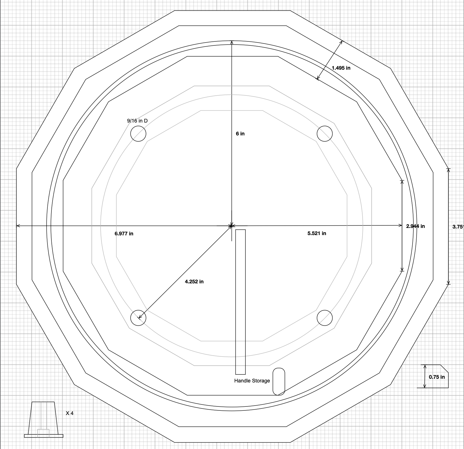
While preparing the orrery for etching and polishing a number of questions arose on the eventual base and dome used for storing and presenting the orrery. The current handle needs some modifications to be able to fit any base large enough for a dome. The orrery is 9.5" in diameter without the handle. I can buy a 10" diameter glass dome that is 9.75" inside diameter. Glass domes are hand made and I am afraid 1/4" is cutting it too close for comfort. The next larger size found is 12". Nothing between 10" and 12" was to be found after many hours of searching on the internet. This means that the base needs to be at least 13" in diameter. After some design work I settled on a 14" base in the shape of a dodecagon. (Of course!)
I have a 3/4" X 11" X 12" piece of red oak that will work well. It will be cut into an 11" dodecagon and surrounded by 1 1/2" of walnut. I have not decided on the joint yet. The walnut dodecagon pieces will be cut from one or two long boards (48" total) so the grain will look uniform. A circular dome groove (12" diameter) will be routed into the walnut after it has been installed. I don't yet know if this will be felted. One additional feature is storage for the handle. It has to be removed when the dome is in place. Two pockets, one long and one short, should suffice. (Again felting is to be decided.) Four brass feet will be made to resemble the column feet on the orrery, but about twice the size. The profile on the outer edge of the base is also 'to be decided.' Four shallow holes will be drilled (9/16" D) to hold the feet of the orrery. The plan is shown in the picture below.
The dimensions shown in the plan are approximations.
| Theoretical Dodecagon Dimensions | |
|---|---|
| Dodecagon Apothem* (r) | Leg Length (6.430781r/12) |
| 5.5" | 2.947" |
| 7" | 3.751" |
* An apothem is the distance from the center of a polygon to the center of its side.
The first challenge is cutting a dodecagon from the 11" X 12" red oak board. A 30° wedge attached to the cross sled would be the simplest way to tackle this job. Five cuts would use the wedge and the other five would use the dodecagon's opposite face. I am not sure how best to manage the depth of cut to result in an accurate leg length. A stop of some type needs to be attached to the sled at a right angle to the wedge. Alternatively, a center point could be fixed exactly 5.5" from the blade. The proto-dodecagon would be rotated around this center in precise increments of 30°. This would completely control both the angle and the side length. Could the angle be accurately set by marking the 30° increments on the board with a compass?
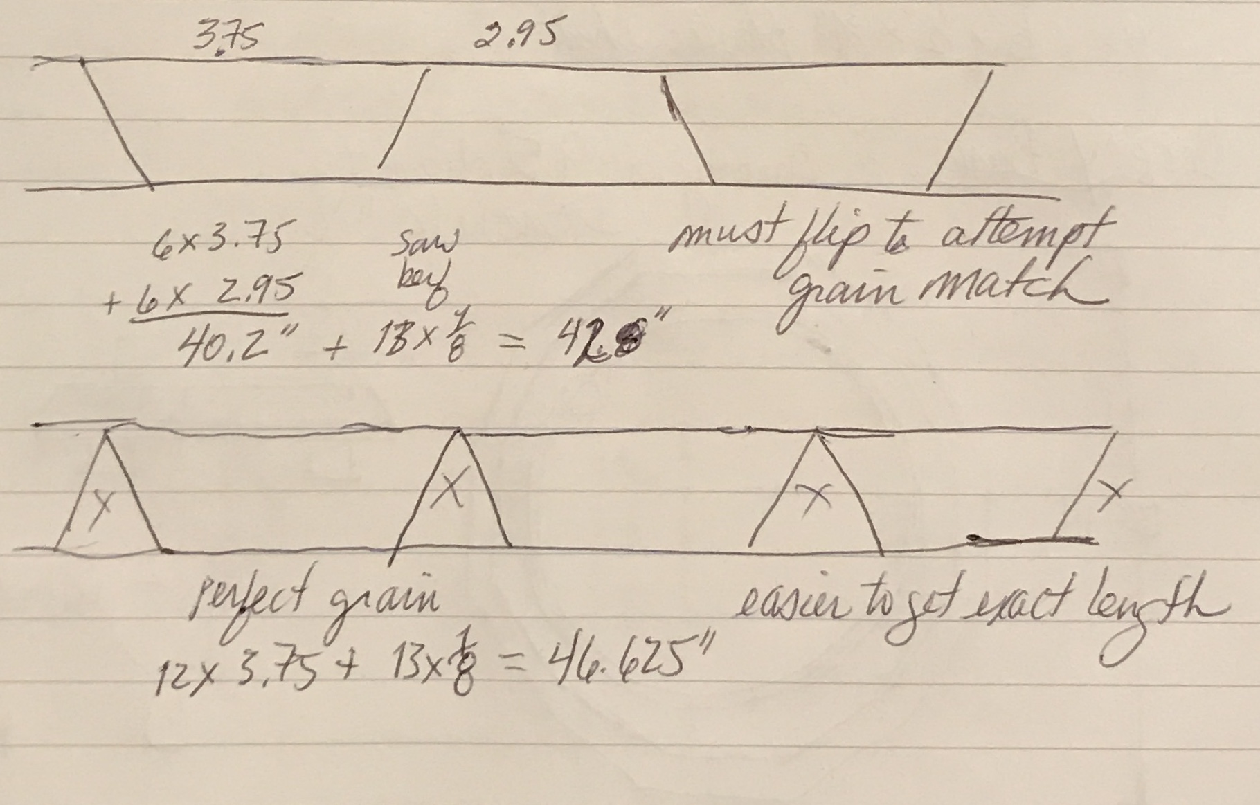
I found a nice walnut board that has 3.75" X 30" of usable wood. It can be split into two pieces that are about 1.75" wide. I need 1.5" plus any extra for the joint. A simple 1/4" lap joint is a possibility. The next step is determining how best to accurately cut the twelve sections of the dodecagon. Two methods were considered. The first is cutting the sections from a long board and alternating the direction of the 30° cuts. This minimizes waste. The board would need to be flipped between adjacent cuts. This uses 42" of wood for the twelve sections. Controlling length requires an accurate stop. The second possibility is to cut twelve parallelograms, i.e. keeping the cuts all going the same direction. This requires almost 47" of wood. A jig would be made for accurately cutting the parallelogram to shape and length. This method insures the grain will flow from piece to piece. A photo of my sketch with the two possibilities is below.
The first thing to tackle is making the inner dodecagon from the 11 1/4" X 11 3/4" cutoff of 3/4" thick red oak. A circumscribed circle needs to be drawn to then use a compass to find the corners of the dodecagon. The apothem or inner radius of the desired dodecagon is 5.50". The following formula gives the circumradius (R) if the inner radius (r) is known.
R = 5.694" or just slightly longer than the inner radius as expected. To find the corners of the dodecagon, first draw the circle with radius equal to the circumradius. Draw a pair of perpendicular lines that intersect at the center of this circle. With the compass set at the circumradius use the four intersections of these lines with the circle to draw arcs that cross the circle at eight points. These points and the intersections with the perpendicular lines are the twelve vertices of the dodecagon.
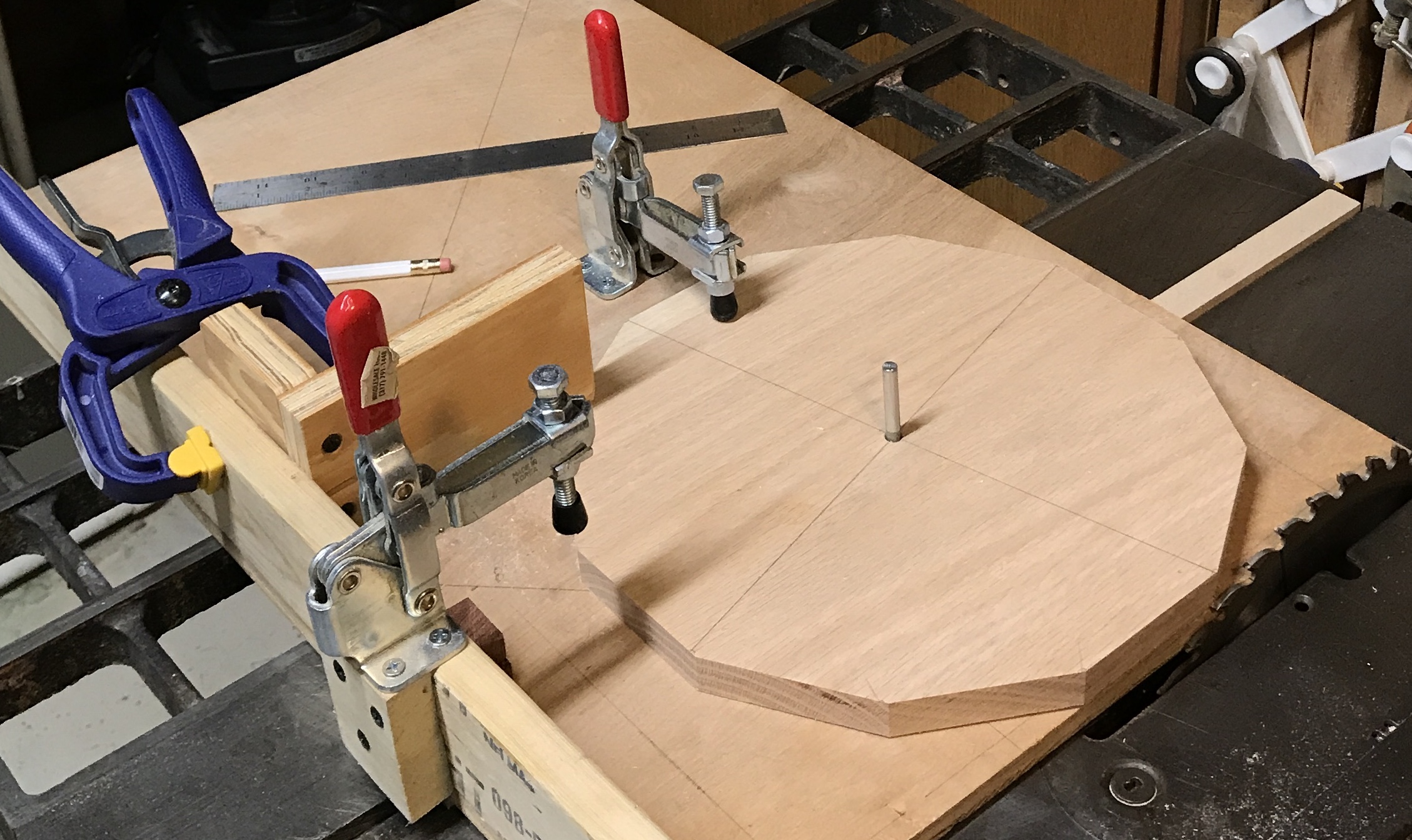
The cross sled was modified to use for cutting the dodecagon. A hole was drilled 5.50" from the blade. A stop from my drill press table was used as a pointer. A clamp was moved near the side of the blank. The first cut was made by carefully adjusting a marked edge of the dodecagon with a straight edge held against the blade. The blank was clamped and the pointer adjusted so it was aligned with one of the marks I had made at each vertex drawn above. The blank was then firmly clamped to the sled. The cut was made and the blank was turned so the next mark was aligned with the pointer. A second cut was made. It was not possible to go all the way around as the corners got in the way of the clamp. So at one point the blank had to be removed from the pin turned and reseated. All of the sides are within 1/32" of 2 15/16". The picture below shows the finished dodecagon still clamped in the jig.
Now for the outer dodecagon. The walnut board had a water damaged end. This was cut off. The two long sides were cleaned up and the resulting 3 1/2" wide board was cut in half producing two boards that are 3/4" X 1 3/4" X 29 1/2". Two cuts need to be made prior to cutting these boards into the dodecagon legs. A rabbet (1/4" X 3/8") needs to be cut in the top of one long side. This will fit in a mating rabbet in the bottom of the dodecagon. The second cut is a decorative cut in the top opposite to the rabbet. I plan to use a simple roundover bit for this cove bead cut.
The first cut was making the rabbets for the lap joint. The blade was replaced with a 3/8" dado setup. The fence was placed so the far side of the dado blade was even with the edge of the blank. The blade was raised about 1/2". The rabbets were cut in the top of both pieces. The fence was then moved to the other side of the blade. The blade was lowered so it was just even with the thickness left in the above cut. The fence was adjusted so it was 3/8" less than 11". The dodecagon was pushed through rotated and this was repeated 11 more times. The lap joint is a good fit. The walnut is a little thicker on the underside, but on top the two boards are even. With the two joints the total width is 13 3/4".
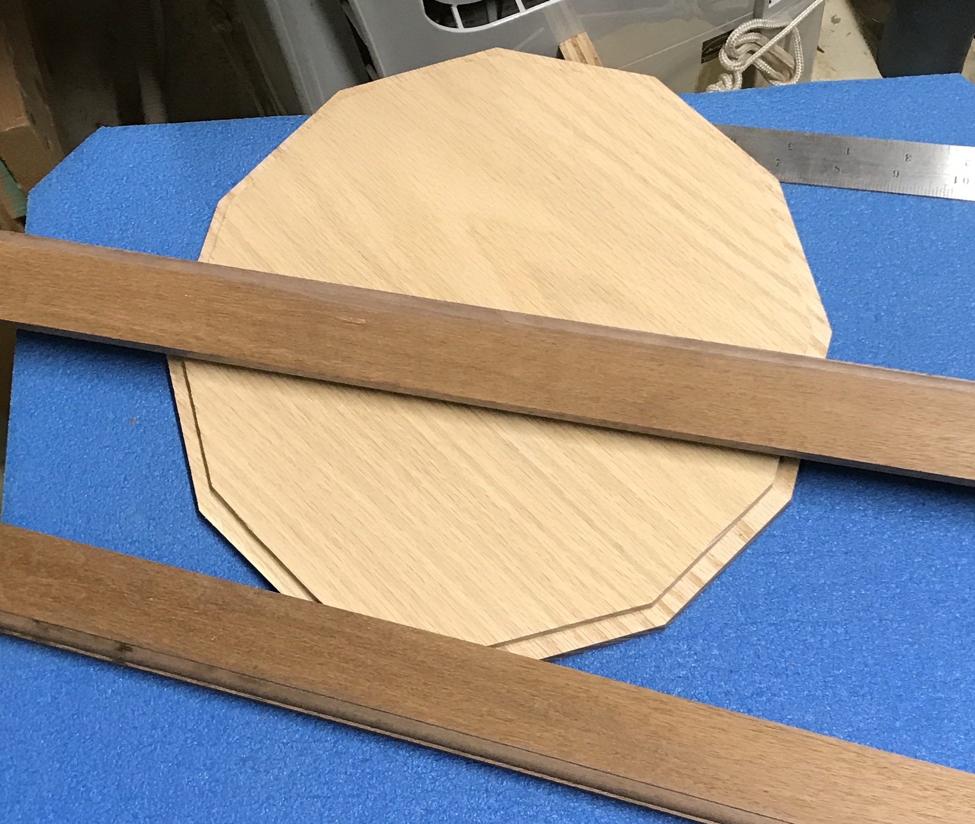
The cove beads were cut this morning. The 1/4" cove router bit was set so both straight edges were barely exposed (from the bottom and from the fence). With the fence set at 9 5/8" the bearing was just even with the fence. A test cut showed the desired profile. After moving some things out of the way the cove beads were cut in both boards. I sanded both boards and the central dodecagon to 220 grit. All three pieces are shown in the photo below.
The first aspect of the setup for cutting the dodecagon frame pieces is setting the 30° angle on the miter. I wrote a quick spreadsheet that gives the sides of a right triangle given the smallest angle and one side length. The spreadsheet gives the lengths in 1/64" increments and provides the error for small sides of the whole number lengths, 1" - 12". Given the two non-hypotenuse sides of a triangle it is very simple to use a framing square to exactly set the angle of the miter. The square short leg is set against the miter and the two lengths chosen are aligned with the XXX. In this case the two 30/60/90 triangle sides selected were 7.000" and 12.125". The error in the length of the long side is 0.0006".
The plan is to cut each of the sections slightly long using approach two from above. The outside length is 3.75", so I will cut each section to 3 13/16" long. Each 29 1/2" board should yield 7 sections with an inch or two left over. These were all cut before I realized my error. The included angle is 30°! These should all be cut at 15°!!!
There was no graceful way to recover from that error. I found a new walnut board that was a little longer and wider. After trimming it two 34" lengths were cut to 1 3/4". The miter was set at 15°, again with the help of the spreadsheet. The side lengths in this case were 5" and 18 5/8" + 1/32". It was a little more difficult to judge the alignment of the longer side with this more acute angle. A stop block was set against the fence and 14 parts were cut. A rabbet was then cut on each piece to match the joint on the dodecagon sides. The router bit height was already set and just the fence needed to be reset. Cope beads were cut on all of the pieces.
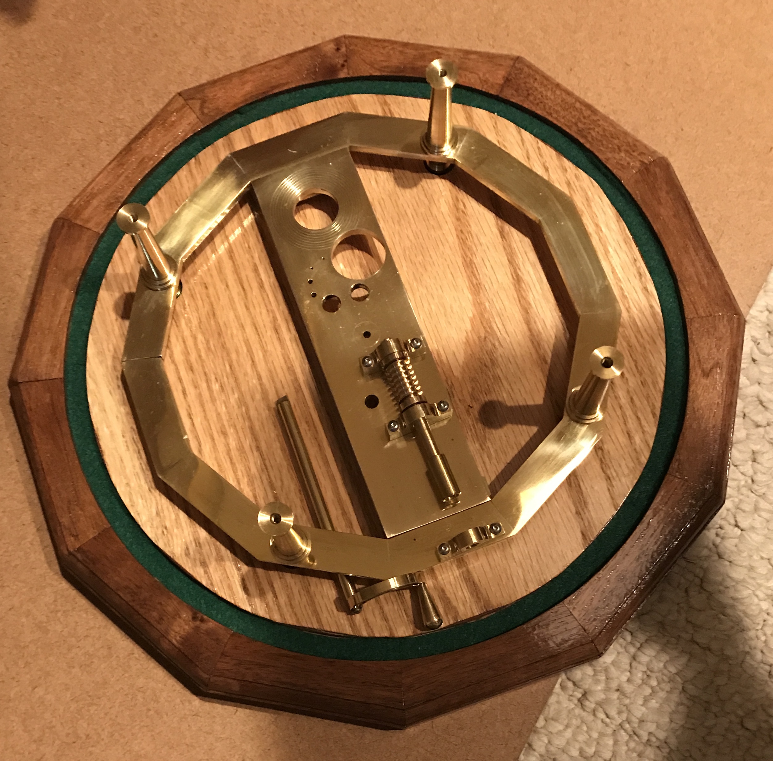
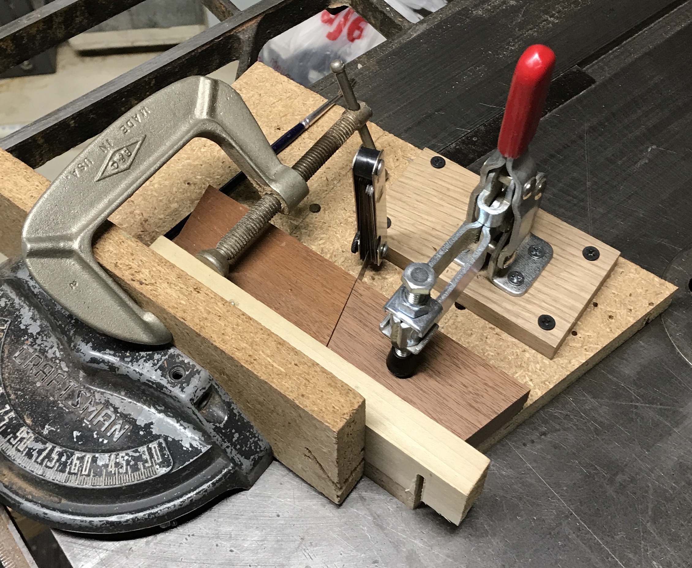
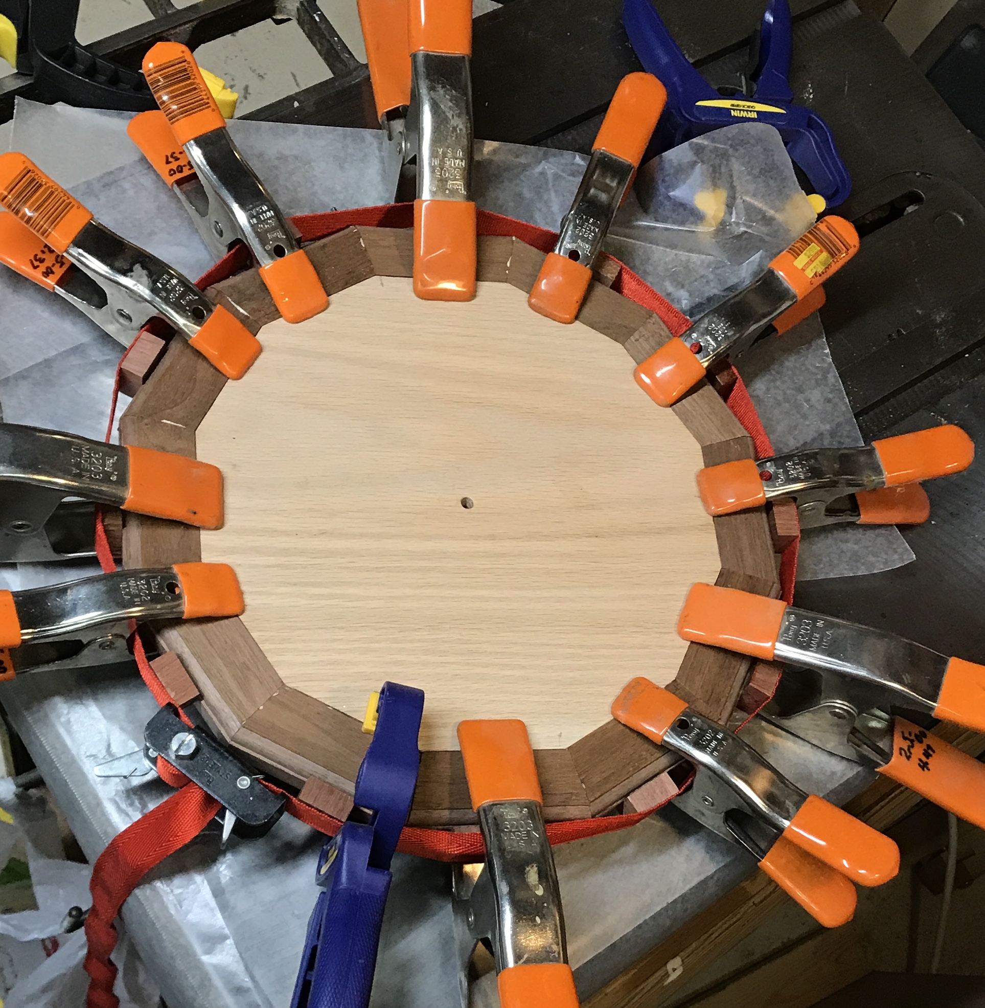
A jig was made to cut the final angle, 15° the other way. A bottom board was screwed to a board vertical along one edge. This vertical board was clamped to the miter gauge. Also attached to the bottom board was a clamp via a 1/2" thick spacer. After cutting the end of the jig at an angle a waste cut off from the previous angle cuts was taped to the jig at the length of the mitered sections to serve as a stop block. The part to be cut was placed against the vertical board and the stop block, clamped in place and cut. All fourteen pieces were cut. The best twelve were placed around the dodecagon. They did not quite fit. The pieces were all a tad long, which had been done purposefully so I could "sneak up on" the final length. A 0.016" feeler gauge was then inserted between the stop block and each piece as it was trimmed. The pieces still did not quite come together around the dodecagon. A further 0.015" was trimmed off of 6 sections by inserting two feeler's (0.016" and 0.015") between the stop and the piece. Great fit!! A picture of the cutting jig with the feeler gauge in place and the final arrangement of sections around the dodecagon are shown below.
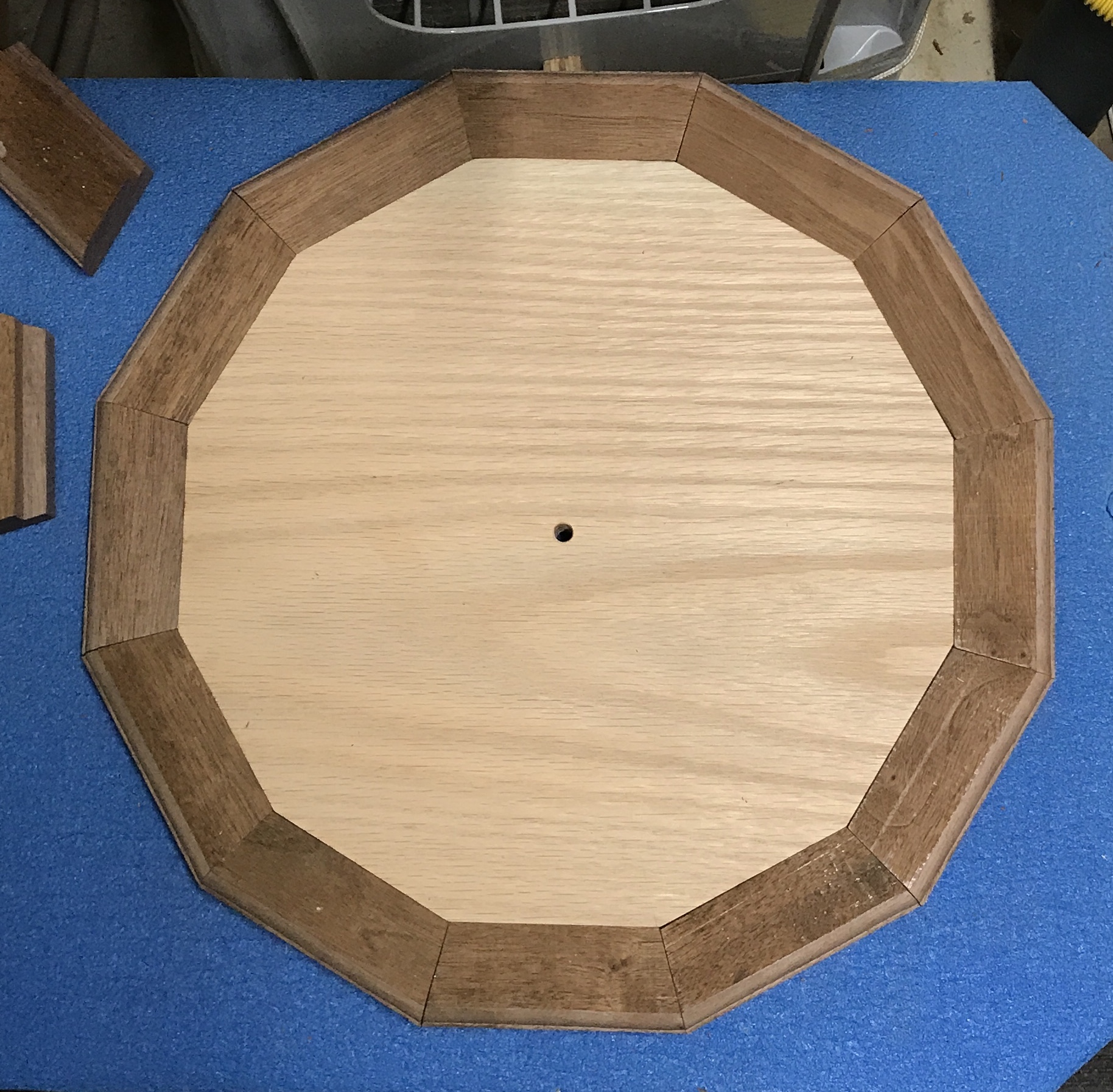
The frame sections were labeled and keyed to the dodecagon. A few of the sections needed to be adjusted with a chisel. Mostly due to the rabbet not being quite deep enough or not even. The twelve sections were then arranged around the dodecagon and clamping was practiced. A strap clamp was used to apply inward pressure. Small wooden blocks were centered between the strap clamp and each section. Pinch clamps provided the vertical compression. Glue was then applied to the joint on the dodecagon. Each section was then coated in glue and pressed into place. Once all twelve sections were in place the strap clamp was applied and tightened. The pinch clamps were then applied all around the assembly, one to each section. The glued up dodecagon frame is shown below.
The picture below shows the outcome of the gluing. There are two sections that did not sit tightly enough against the dodecagon. I found a very thin strip of the walnut that slid into the gaps. It was glued into place prior to sanding. The only other issue is the routed edges do not always meet evenly.
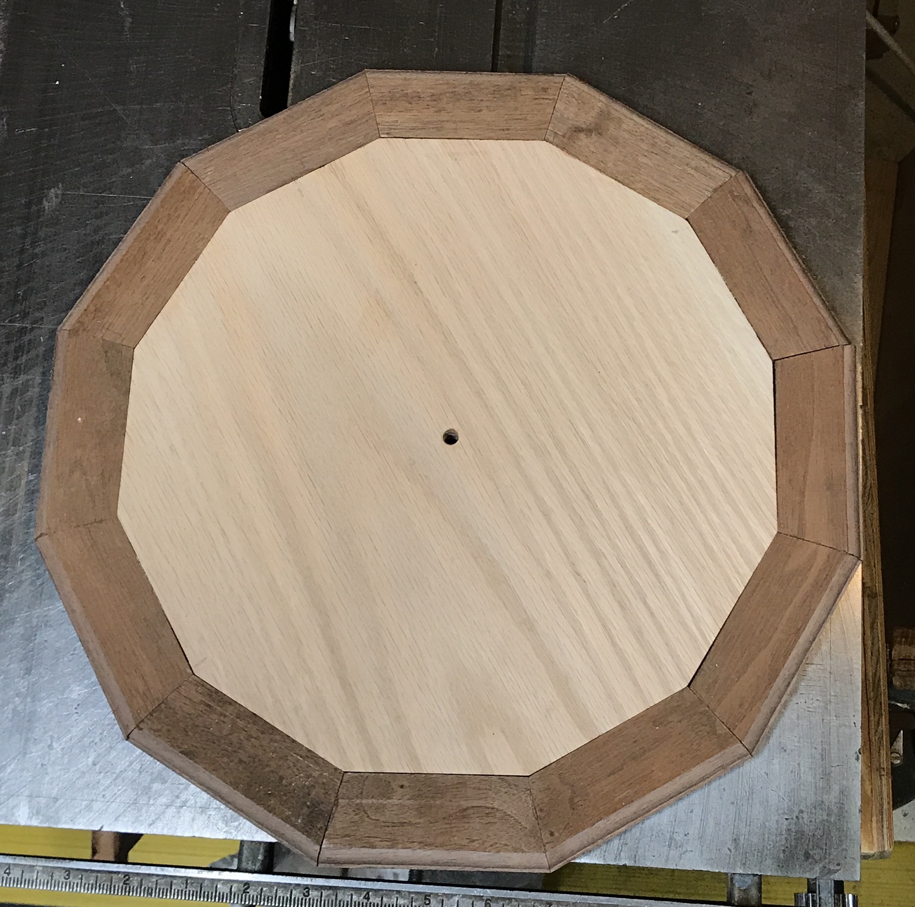
Used the chisel to clean up the gaps filled with the thin strips. The other gaps were filled with glue and the top surface of the frame was sanded with 100 to 220 grit paper. The gaps are no longer readily apparent. The unevenness at some of the joints on the routed surface was tackled next. The corners were sanded by hand with 100 grit paper until the corner was evened up. The routed surfaces were then sanded with 150 grit paper. Dust was removed from the base by vacuum. The groove for the glass dome will be routed when it arrives in about a week. I am not sure, until it arrives, how wide the groove should be. I am also considering felting the bottom of the groove. Holes for the orrery's feet will also be drilled and felted at that time. A picture of the sanded base is below.
The dome arrived a couple of days ago. I measured it this morning. It is 11 3/4" in diameter and 5/32" thick. The plan is to use a 1/4" router bit to make the circular groove in the base to a depth of 1/4". The outside edge needs to be slightly outside of the dome. The dome will be outlined on the base and the router bit set to remove the pencil line. The pencil line will also let me check for circularity.
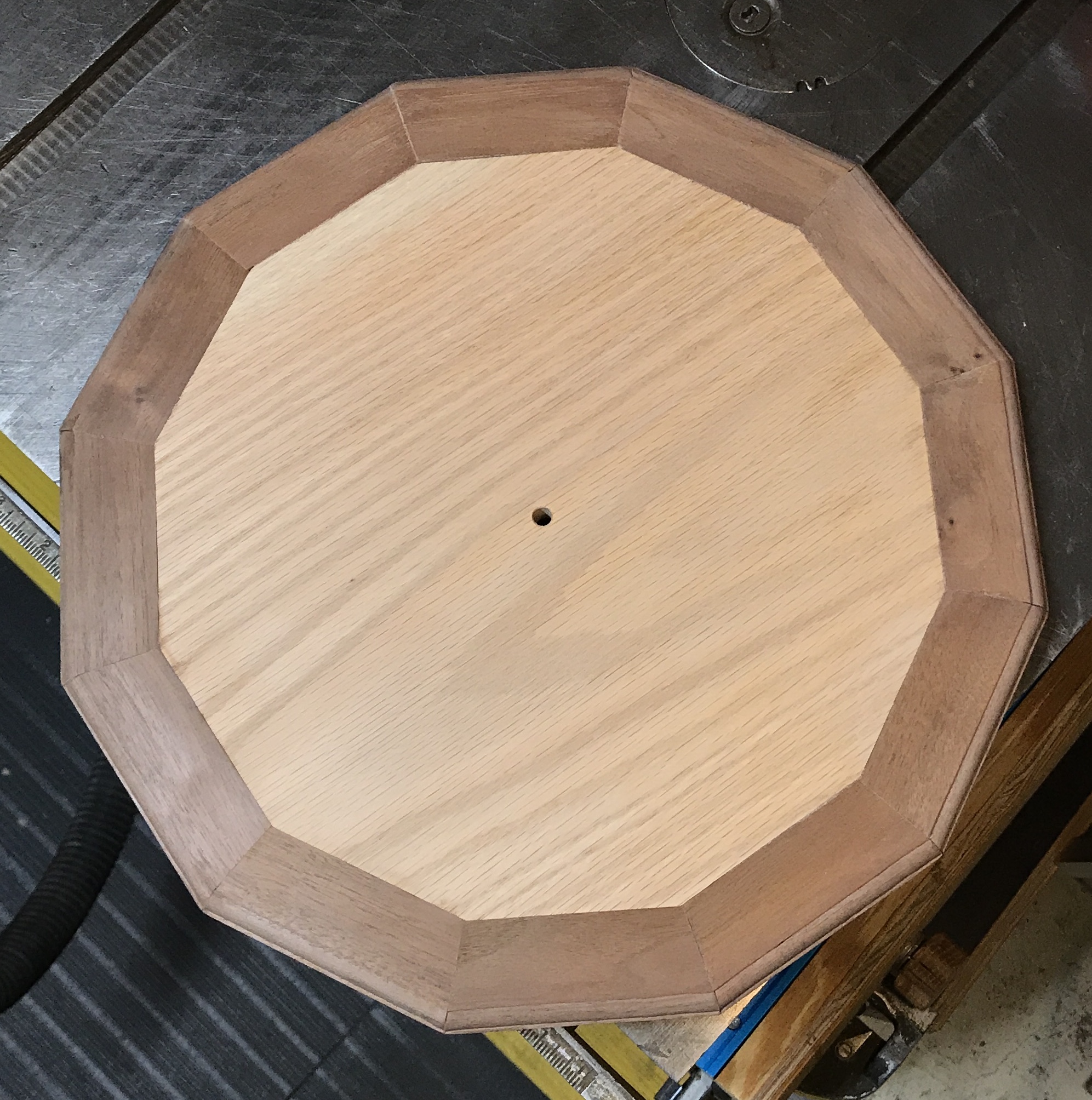
The pencil line was drawn around the dome after centering it on the base. The hole in the base is 1/4" and the router jig uses a pin that is 0.151". A 1" long adapter was quickly made that is 1/4" diameter and has a 5/16" deep 0.152" diameter hole. The adapter was placed in the hole. (Had to center it over the slot in the table saw.) The base was taped to the table saw with double sided tape. The distance was measured set on the router jig and the 1/4" bit was exposed 1/4". The router was turned on and the pin was placed in the hole. (Not a trivial process.) The router was turned around the circle. After removing the router it was clear that the outside of the bit was about 1/16" shy of the pencil line. The router jig was adjusted and a second circle was cut. This looked much better. There was one 'jog' on the inside of the circle where the router was initially started. This was removed with a chisel. The inside of the circle in this spot was sanded and then the edges were lightly sanded.
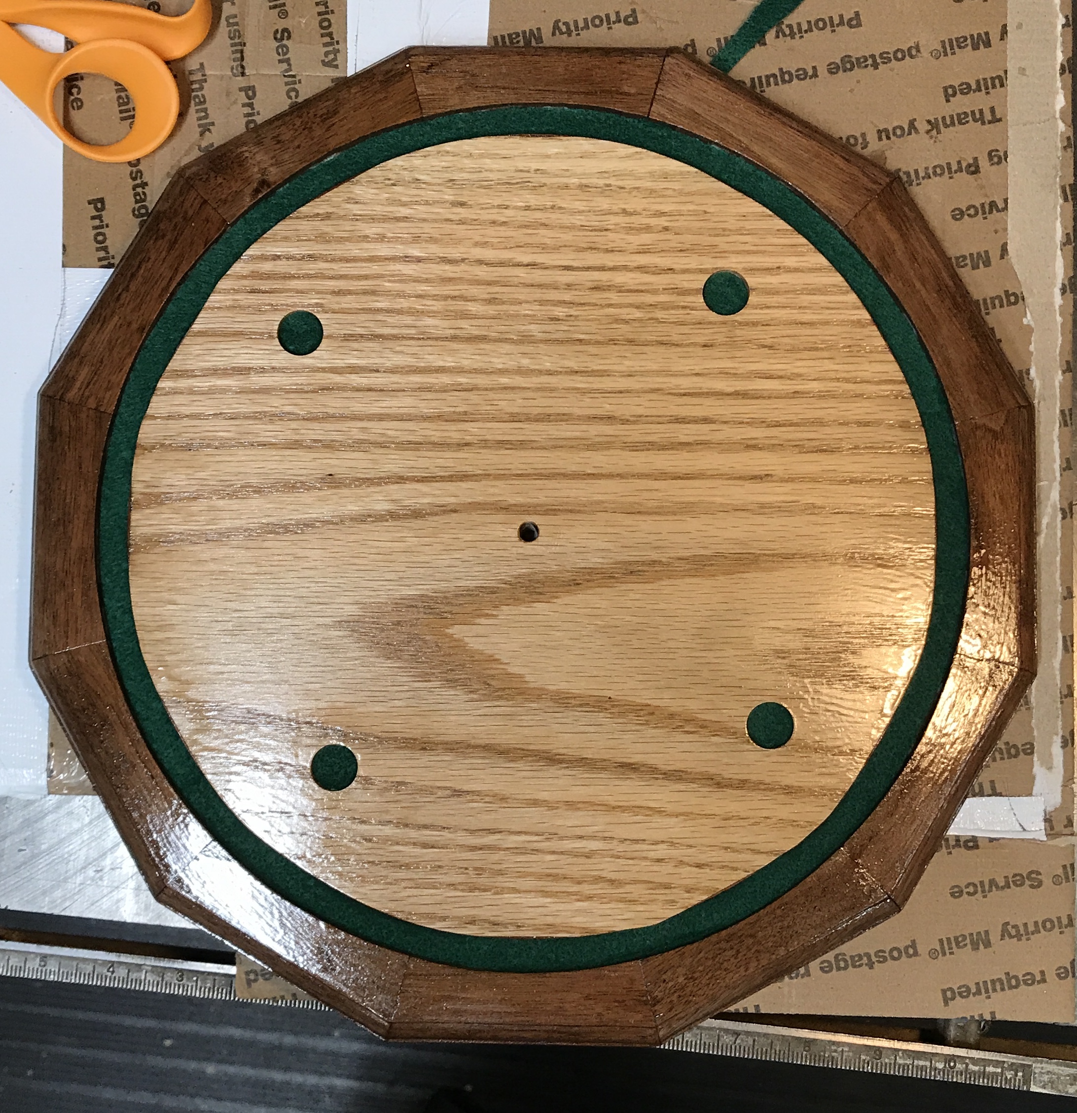
The dome fit nicely. The whole base was lightly sanded with 220 grit paper and then vacuumed of dust. The bottom dodecagon frame was centered on the base and the dodecagons were aligned. The four holes for the columns/feet were marked on the base. The holes were center punched. The bottoms of the feet are 1/2" in diameter, so a 5/8" Forstner bit was used to drill the holes to 1/8" depth using the stop on the drill press.
After a final cleaning to remove dust a thin coat of shellac was applied. This was allowed to dry for one hour. The base was sanded lightly with 220 grit paper, cleaned of dust and a second light coat of shellac was applied. This was repeated for a third time and the base was left to dry overnight. I am not thrilled with the final coat of shellac. It is rather bumpy!
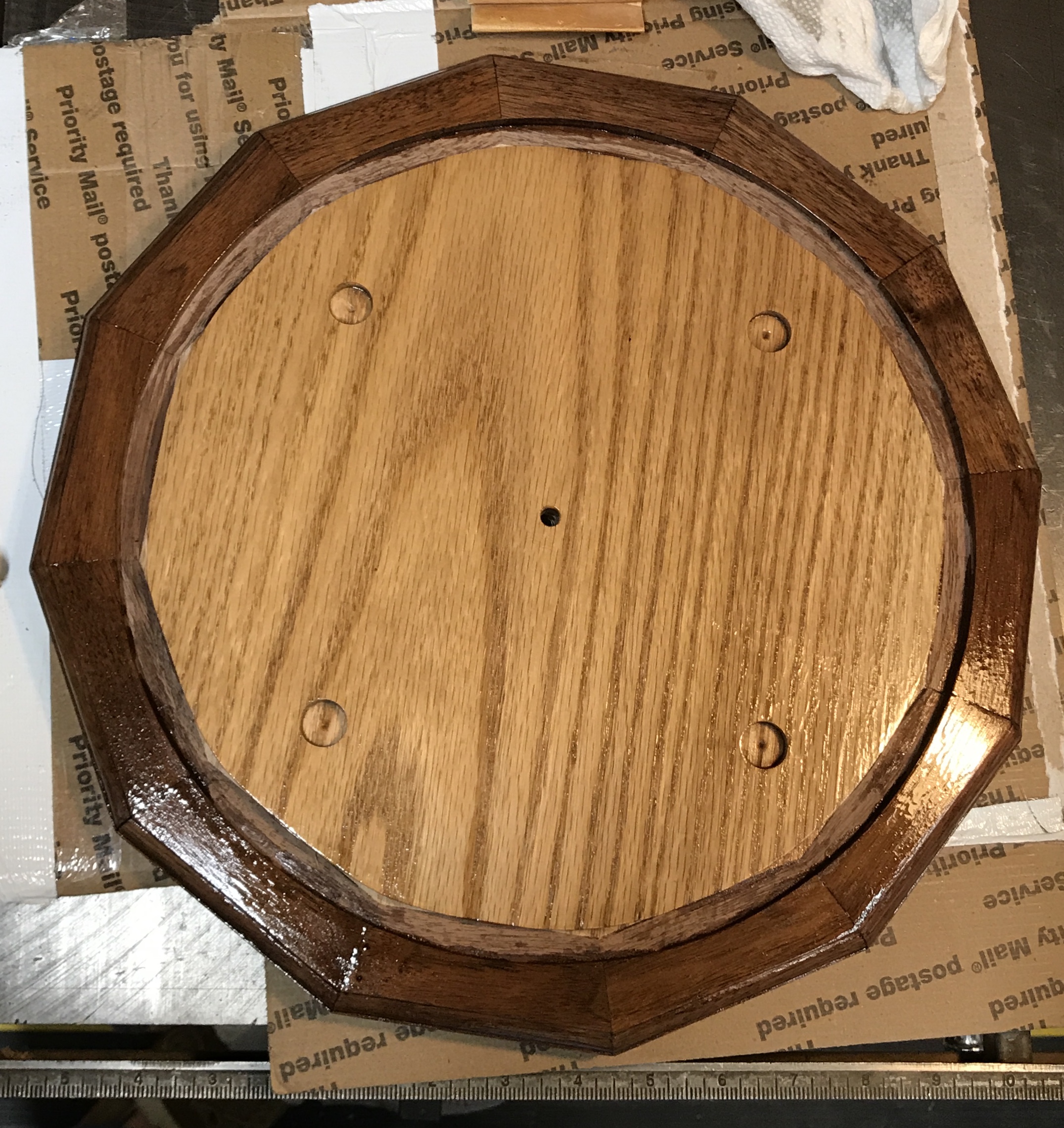
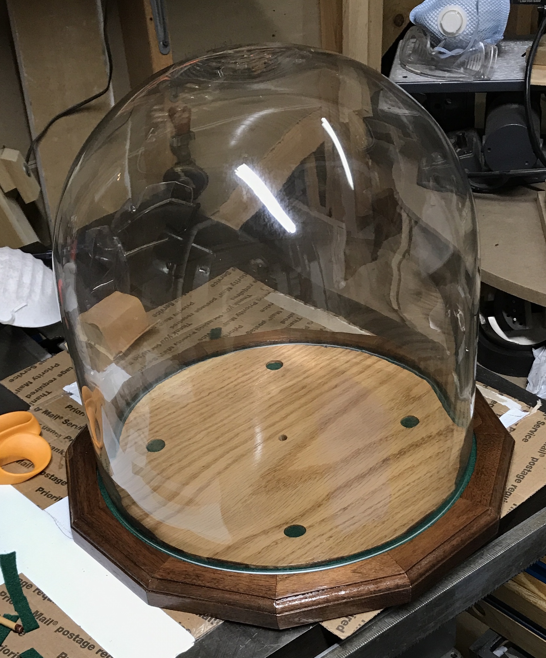
The orrery base was felted. Four 5/8" circles were cut from the green felt left over from the machinist's tool chest. Thin strips were then cut to fill the dome's groove. All of the pieces were glued in to the depressions with wood glue. A picture of the finished product is shown below. Alongside it is a picture of the base with dome.
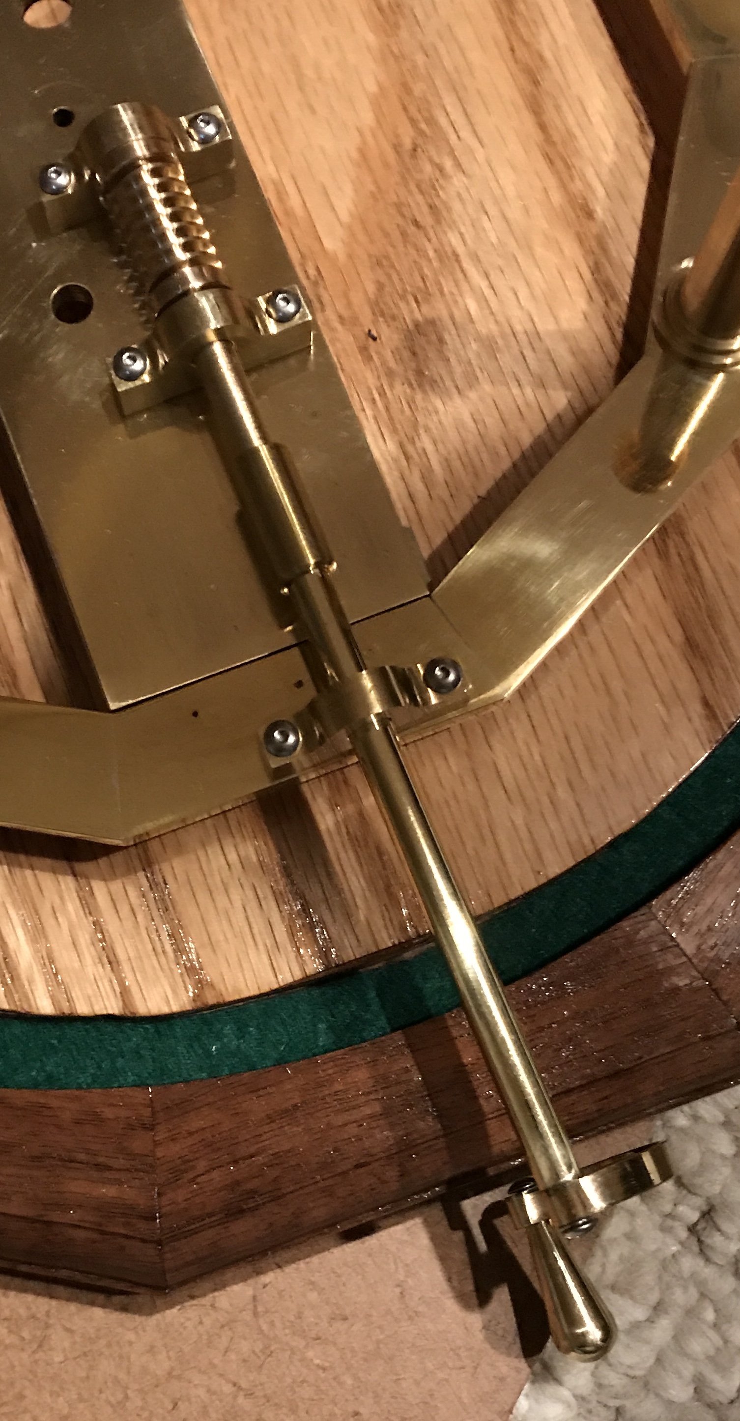
Because the base is wider than originally expected, due to the size of the dome, one additional change needs to be taken care of. The current shaft that attaches the handle to the worm shaft is 2" long. To get outside of the new base it needs to be 4" long. The handle cannot be in place when the dome covers the orrery. A different means of attaching it to the worm shaft must be found. Two simple modifications of the ends of the shafts should solve the attachment issue. A slot in the worm shaft coupled with a flat on the the handle shaft should suffice.
The handle shaft was made first. A 4 3/16" length of 0.25" brass rod was cut with a hacksaw. One end was faced, drilled and tapped 4-40 to a depth of 1/4". The end was chamfered. The rod was measured and the other end was faced so the rod was 4 1/8" long. The end was chamfered.
The rod was transferred to the vise on the mill. The end mill was aligned with the top and the end of the rod. The end mill was lowered 0.095" and 0.015" increments of metal were cut from the end producing the first flat. The depth of this flat is 0.125". The rod was rotated 180° in the vise. A ruler was placed under the first flat and the rod adjusted until the ruler was level by eye. The end mill was again moved so it just touched the top. It was lowered 0.095" and cuts were made across the face of the shaft to a depth of 0.125". This left a 0.054" wide tongue across the end of the shaft.
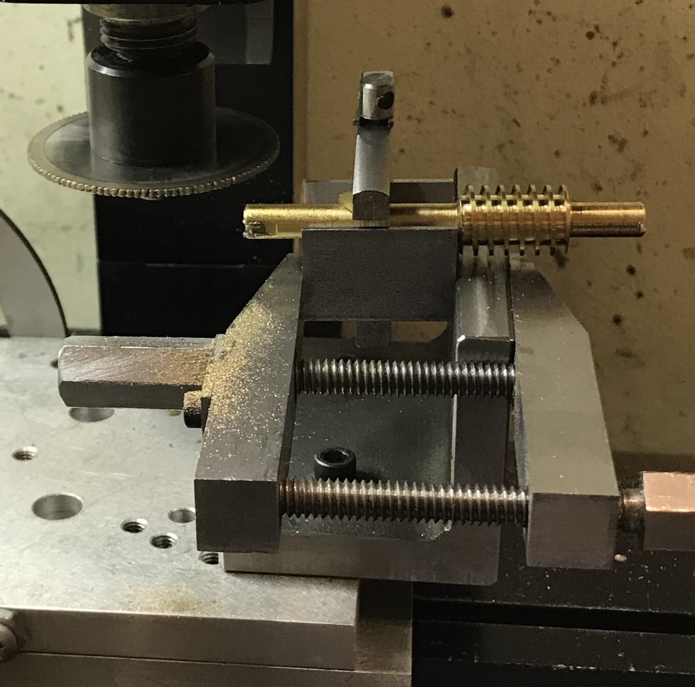
The worm shaft was modified next. The worm was clamped to a small vee block. The vee block was clamped to the angle plate. Because this left the shaft was too low for the slitting saw, the angle plate was attached to the sine plate. The sine plate was attached to the mill table. The mill table was attached to the... This jury rigged setup is shown in the photo below. A 0.057" slitting saw was aligned with the top of the shaft and then lowered 0.151" putting the saw bottom at the bottom of the planned slot. The groove or slot was cut to a depth of 0.125" in 0.010" increments. When the tongue was inserted in the slot the bottom of the handle shaft rode just below the bottom of the worm shaft by feel. The slitting saw was raised about 0.010" and the slot was widened. The slot was deburred. The previously made coupling was placed on the worm shaft and a set screw installed. The new handle shaft fit smoothly and easily rotated to align with the slot.
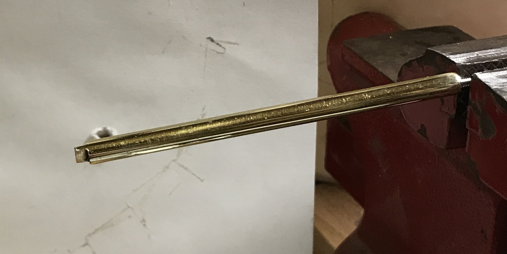
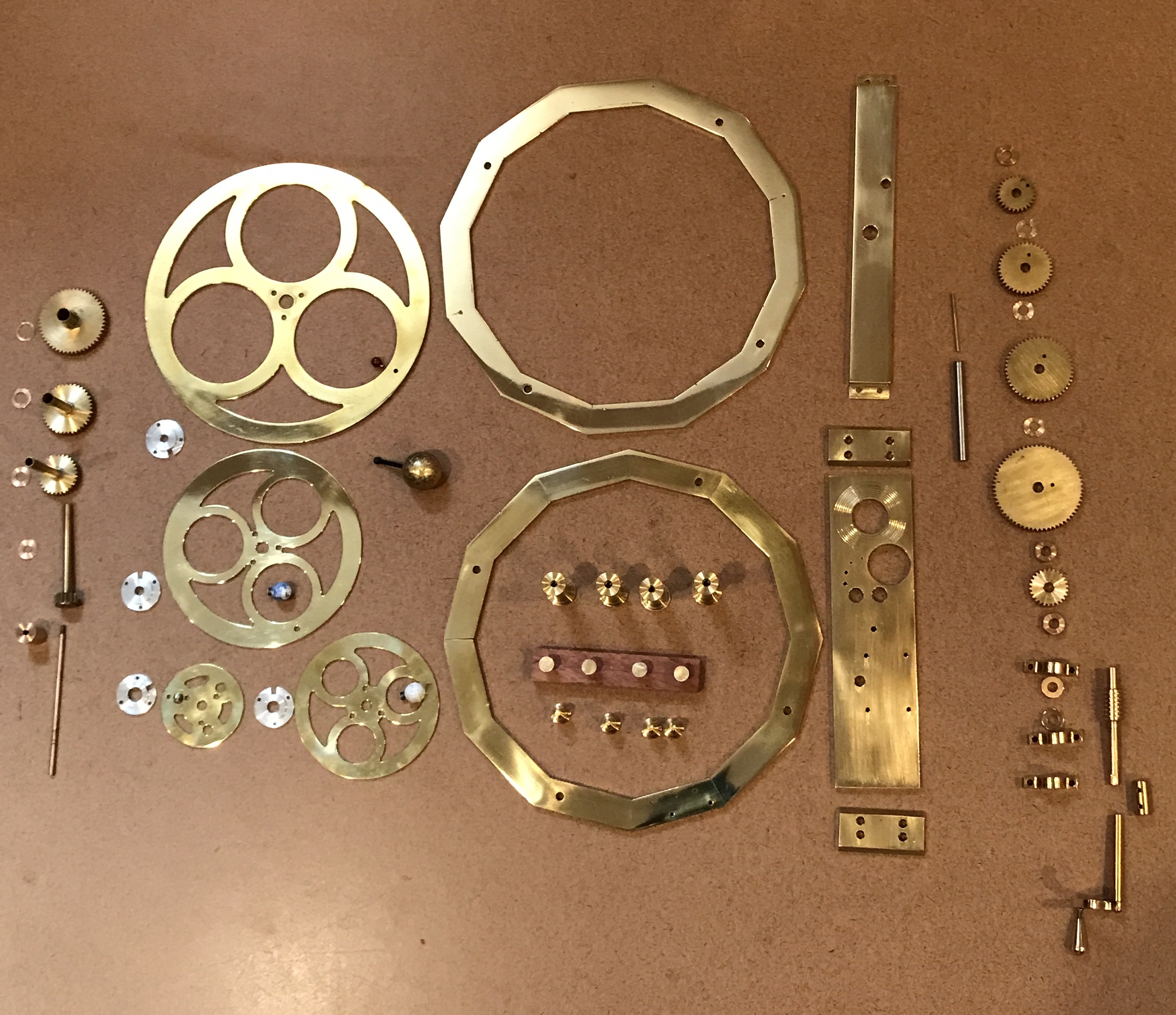
The final step was finishing the handle shaft. It was polished without any sanding using red rouge on the cotton buffing wheel. It was then neutralized with NaHCO3, rinsed with water and dried with an acetone rinse. Two coats of EverClear varnish were applied. The last part for the orrery was now complete. A picture shows the shaft during varnishing. The second picture shows all of the orrery parts except this shaft.
The new shaft works well. Below is a picture of it installed. There is a good gap between it and the base. The second picture shows how it can be stored when not in use. The dome fits nicely around it. I have decided not to make a groove for handle storage. A slot for the handle would join the dome groove and that would not look appropriate.